
When customizing a LCD display module, it is particularly important to confirm the interface type. Otherwise, using the wrong interface type and corresponding parameters can result in consequences ranging from not being able to obtain the desired display content and display area to causing the LCD screen to burn out and be directly scrapped.
So if you want to customize a LCD module, you must be familiar with the interface of the LCD module, confirm the interface type, pin order, and related parameters. Today, we will provide you with a brief overview of LCD interface classification and a detailed explanation of LVDS and eDP interfaces.
Interface Definition and Classification
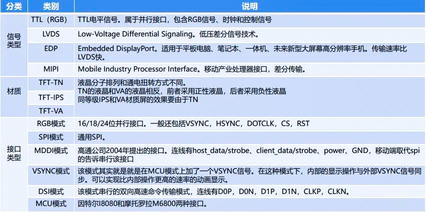
The LCD screen interface refers to the connection between the controller and the LCD module. Through the LCD screen interface, the controller can control the brightness, contrast, color and other parameters of the LCD module, thereby achieving image display. Common LCD screen interfaces include TTL, LVDS, EDP, MIPI, etc.
Interface classification
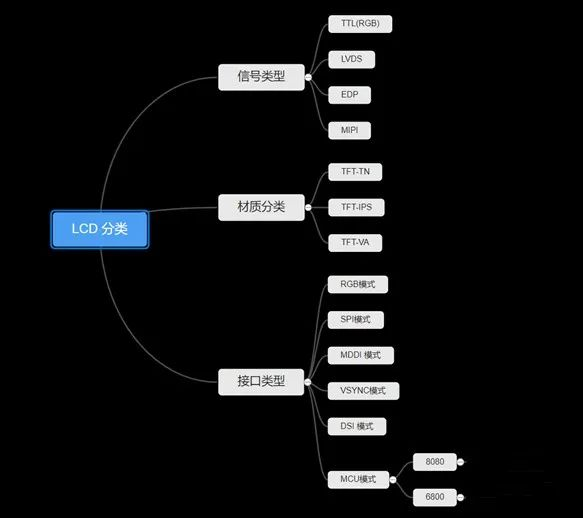
Classified by signal type: TTL/LVDS/EDP/MIPI
Classified by material: (for TFT-LCD) TFT-TN/TFT-IPS/TFT-VA.
The interface types are divided into RGB mode, SPI mode, MDDI mode, VSYNC mode, DSI mode, MCU mode, etc.
Principles for selecting interfaces
When designing and using a screen, we first evaluate whether the AA area (visible area), peripheral size, and basic parameters of the LCD screen meet the requirements. We also need to select the interface mode suitable for the communication end of our host based on the motherboard. The applicability of the interface mode directly determines whether this LCD screen can be used, and of course, it can also be paired with HDMI, VGA DVI driver board to solve this problem.
At present, there are many commonly used interfaces for LCD screens. It is important to pay special attention to whether the interfaces are compatible with the corresponding motherboard, otherwise an additional driver board will be required, which will also affect the overall structural design.
The application scope of different interfaces may vary, mainly based on transmission rate and requirements for image quality:
MCU: commonly used for displaying still images with low transmission speed requirements
RGB: commonly used in small and medium-sized sizes, with certain requirements for transmission speed, can be used for displaying videos or animations, generally less than 800 * 600
LVDS: Commonly used for products with medium to large sizes and high transmission rate requirements
MIPI: commonly used for products with high resolution and high transmission rate requirements, such as mobile phones
EDP: Commonly used for products with high transmission rate requirements, such as tablets, laptops, all-in-one machines, etc
This issue introduces you to the commonly used interface types LVDS and EDP interfaces on the market.
LVDS interface
LVDS (Low Voltage Differential Signal) refers to a low voltage differential signal.
The characteristic of LVDS is current driven mode, with a voltage swing of 350mV loaded on a 100 Ω resistor.
The advantages of LVDS include high-speed transmission, low noise, low power consumption, and low voltage.
1. Low voltage differential signal
LVDS (Low Voltage Differential Signal) is a low voltage differential signal widely used in LCD screen interfaces. A key feature of this interface, which is commonly used for internal image transmission in LCD displays today, is that it is differential.
This means that the signal is not disturbed and we can use a pair of twisted pairs to transmit data. We can quickly send data without being damaged by any noise or interference. This type of data corruption is common in other interfaces.
2. Current drive mode of LVDS
The sending end is a 3.5mA current source, and the generated 3.5mA current flows through one of the differential lines to the receiving end. Due to the high resistance of the receiving end towards DC, the current passes through the matching resistance of 100 Ω at the receiving end to generate a voltage of 350mV, and at the same time, the current flows back to the sending end through another path of the differential line. When the sending end undergoes a state change, effective '0' and '1' states are generated by changing the direction of the current flowing through a 100 Ω resistor.
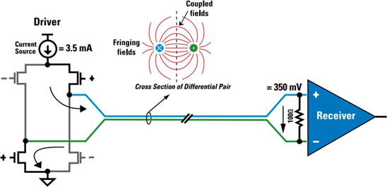
▲ LVDS driver and receiver
It is current driven and obtains voltage by placing a load on the receiving end. When the current flows forward, the receiving end outputs 1, and vice versa.
LVDS signal transmission consists of three parts: differential signal transmitter, differential signal interconnect, and differential signal receiver.
Transmitter: Converts unbalanced TTL signals into balanced LVDS signals. There is a distinction between independence and integration. Receiver: Converts the balanced transmission LVDS signal into an unbalanced transmission TTL signal with high input impedance. Interconnector: includes connecting wires (cable or PCB wiring), and terminal matching resistors. According to IEEE regulations, the resistance is 100 ohms. We usually choose 100120 euros. 3. Advantages of LVDS
(1) High speed transmission capacity and low swing: The constant current source mode and low swing output of 350mv LVDS technology mean that LVDS can drive at high speed, for example, for point-to-point connections, the transmission rate can reach 800Mbit/s.
(2) Low noise/low electromagnetic interference
LVDS signal is a low-voltage differential signal. We know that differential data transmission has stronger resistance to common mode input noise than single line data transmission. On two differential signal lines, the direction of current and voltage amplitude are opposite, while the receiver only cares about the difference between the two signals. Therefore, when noise is coupled to both lines in a common mode manner, it can be cancelled out, and the electromagnetic fields around the two signal lines also cancel out each other.
Therefore, the electromagnetic radiation transmitted by two differential signal lines is much smaller than that transmitted by TTL single line signals. Moreover, the constant current source driving mode is not easy to generate ringing and switching spikes, further reducing noise.
(3) Low power LVDS devices are generally implemented using CMOS technology, therefore they have lower static power consumption. The power consumption of LVDS load (100Q terminal resistor) is only 1.2mW. LVDS adopts a constant current source mode driving design, greatly reducing the impact of frequency components on power consumption.
(4) The low-voltage LVDS interface adopts low-voltage differential signal technology, and its transmission and reception do not depend on the power supply voltage, such as 5V. Therefore, LVDS can be easily applied in low-voltage systems, such as 3.3V or even 2.5V, while maintaining the same signal level and performance.
LVDS is also easy to match with terminals. Usually, a 100 Ω matching resistor as close as possible to the receiving input across the differential line can provide good matching and optimal signal quality.
The distance between the 100 ohm resistor and the receiving end should not exceed 500mil, and it is best to control it within 300mil.
With the development of information technology, LVDS has the advantages of high performance, low power consumption, low noise, and low voltage, making it a suitable solution for many designs.
EDP interface
The eDP interface uses simpler connectors and fewer pins to achieve high-resolution signal transmission, and can achieve simultaneous transmission of multiple data, thus its transmission rate is much higher than LVDS. EMI anti electromagnetic interference is also very excellent, and when there are high requirements for this aspect and the LCD screen resolution is required, the EDP interface can be selected. We call it the new LVDS.
The eDP interface is a fully digital interface based on the Display Port architecture and protocol, which can transmit high-resolution signals with simpler connectors and fewer pins, and the data transmission rate is much higher than LVDS.
EDP has three basic architectures, including the main channel (Main Link) for audio and video transmission, auxiliary channel (AUX), and hot swappable (HPD).
The screen interface of the eDP screen cable is a 0.3-0.5 small pitch welded flat wire, and the EDP channel classification can be divided into single channel and dual channel. EDP screen wires generally consist of 2, 3, 5, and 8 twisted pairs, while common EDP screen wires are 2 or 3 signal twisted pairs. Current common rates: 1.62Gbps/LANE, 2.7Gbps/LANE, 5.4Gbps/LANE
Data transmission signal: LANE0/1/2/3
Communication interface: AUX hot plug detection interface: HPD version: EDP1.2/1.3/1.4
Features:
1. The eDP protocol is an extension of the embedded architecture and protocol for DP applications, so it is fully compatible with the DP protocol; 2. The eDP interface is an internal interface that can be used for transmission between chips or between display screens and driver boards; 3. Due to its ability to achieve high-speed simultaneous transmission of multiple data and low electromagnetic interference, this type of interface is gradually replacing the traditional Low Voltage Differential Signal (LVDS) interface. Taking a color LCD screen with a resolution of 1920x1200 and 24 bits as an example, if LVDS interface is used, 20 pairs of data transmission lines are required; If using eDP interface, only 4 pairs of wires are required. It can be seen that the advantages of eDP interface are quite obvious, especially in high-definition screens. EDP has high bandwidth, good integration, and simple product design. This interface has been widely used in other integrated display panels and image processors such as laptops, tablets, and mobile phones. The eDP interface reduces device complexity, supports essential functions for critical cross industry applications, and provides performance scalability to support next-generation displays with higher color depth, refresh rate, and display resolution. The eDP interface is rapidly becoming a mainstream interface.
How interfaces will evolve in the future
Although both of these interfaces are currently mainstream in displays and can also meet current and future transmission bandwidth requirements.
But we believe that with the increase in consumer demand and the pressure of market competition, future interfaces will continue to innovate.
The development direction of future interfaces: people-oriented, experience first!

